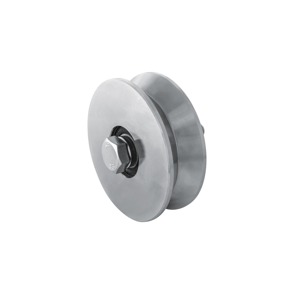
101.100
Zinc-plated V-groove wheel with bolt and two bearings for a track-mounted sliding gate. The published diameter for product reference 101.100 is 98 mm. Groove profile and mounting must be matched to the installation's track.
Manufacturer documentation ↗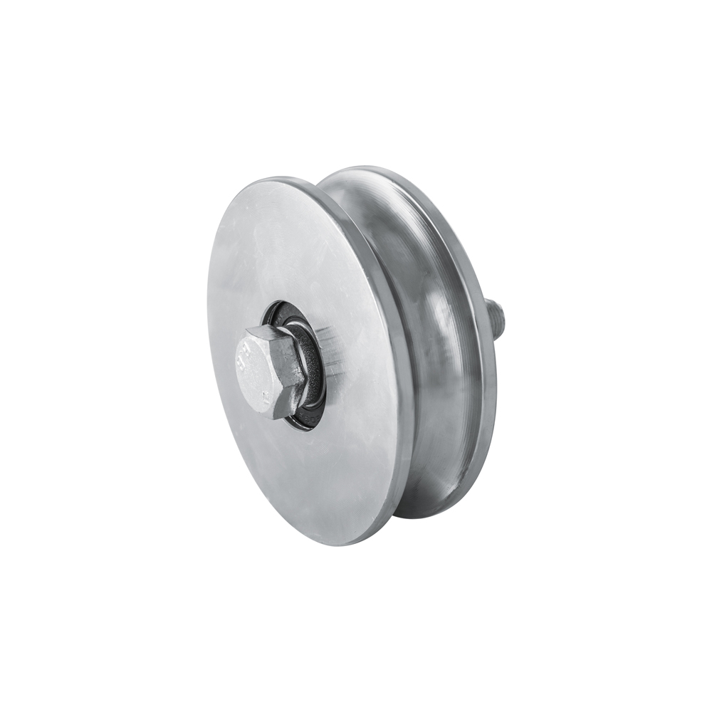
104.100
Zinc-plated semicircular-groove wheel with bolt and two bearings, for track-mounted sliding gates. Product reference 104.100 has a diameter of 98 mm in the manufacturer's table. The track shape must match this round groove.
Manufacturer documentation ↗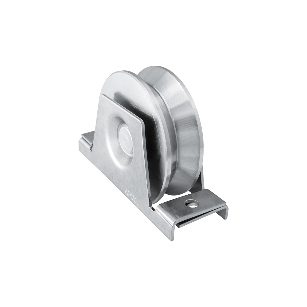
110.100
Zinc-plated V-groove wheel supplied with an internal support and two bearings. Reference 110.100 is offered with a diameter of 98 mm. This construction clearly distinguishes the internally supported wheel from bolt-only models.
Manufacturer documentation ↗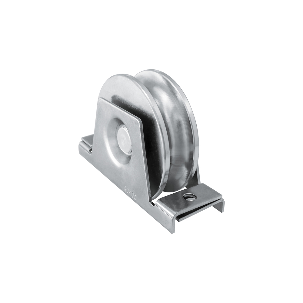
113.100
Zinc-plated half-round-groove wheel with internal bracket and two bearings for sliding gates. The diameter stated for 113.100 is 98 mm. Select this model according to rail profile and space available at the bottom of the gate.
Manufacturer documentation ↗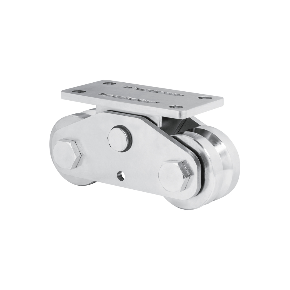
153.80.B
Assembly with two V-groove wheels, mounted on a rocker with a drilled mounting plate. Product reference 153.80.B uses 78 mm diameter wheels. The plate configuration distinguishes it from the range's weld-on versions.
Manufacturer documentation ↗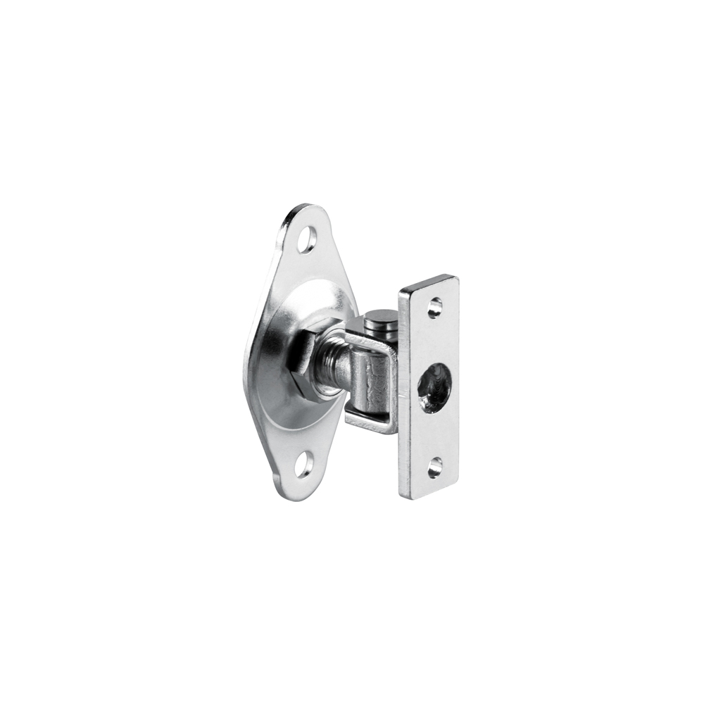
417.18
Adjustable upper hinge for swing gates, comprising a bracket and a two-hole mounting plate. Reference 417.18 is identified as M18 in the Hi-Motions table. Selection must account for available fixings on the post and leaf.
Manufacturer documentation ↗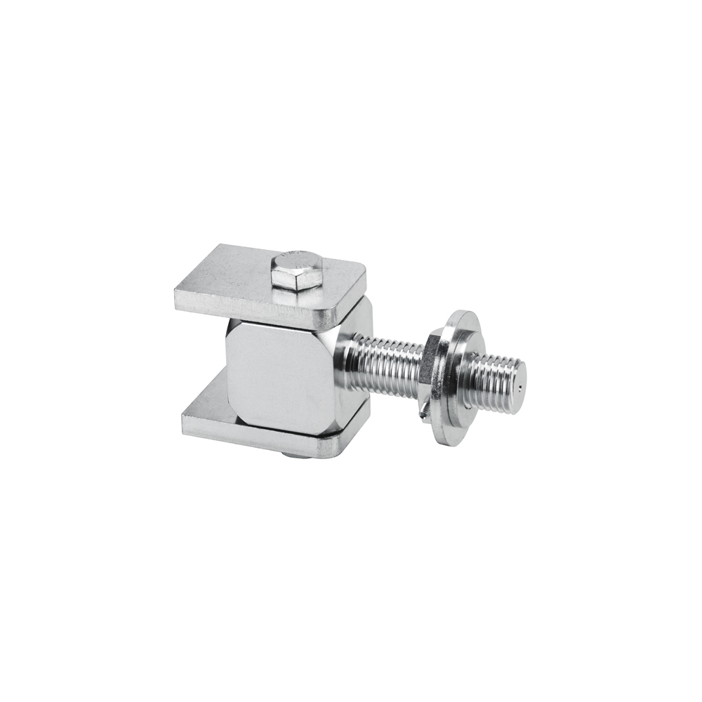
429.30
Upper hinged gate hinge with two bearings and an adjustable sleeve. Hi-Motions publishes reference 429.30 with module M30. This construction differs from simple hinges and must be selected according to installation and leaf adjustment needs.
Manufacturer documentation ↗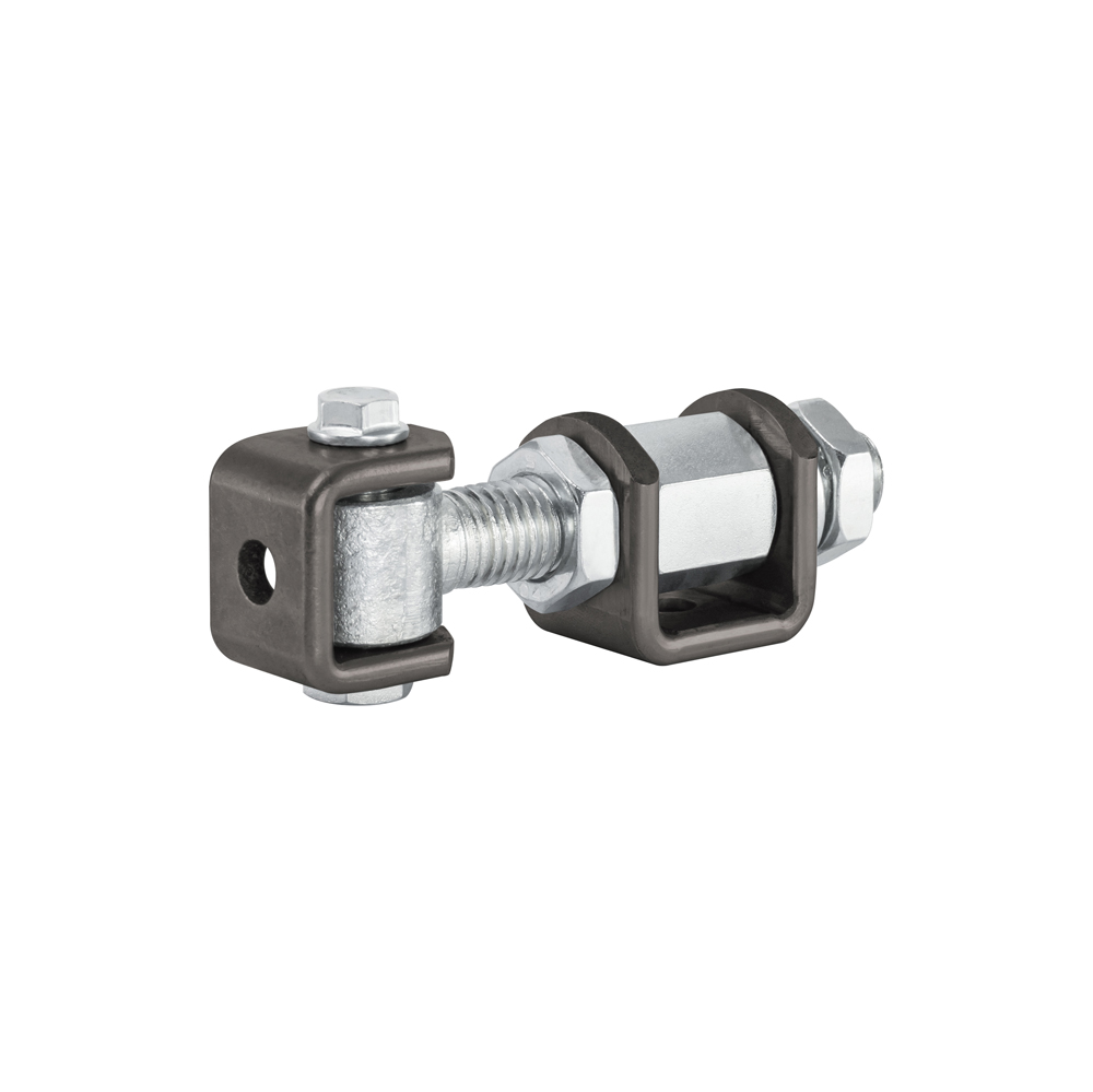
432.2
Adjustable hinge from series 432.2, presented by Hi-Motions for 180-degree opening. The manufacturer's table states module M18. The achievable gate angle also depends on hinge positioning and clearances around the leaf.
Manufacturer documentation ↗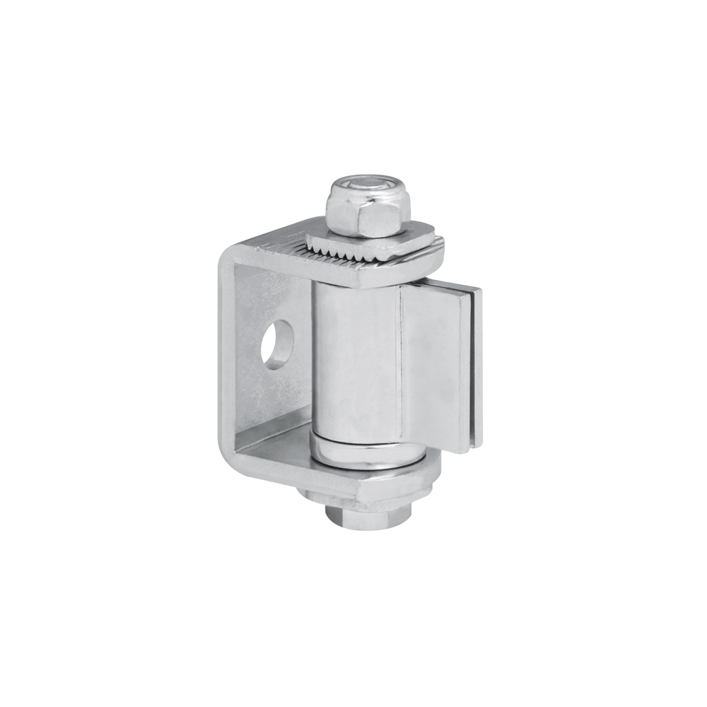
444.0
Adjustable bearing hinge for swing gates, identified by the unique product reference 444.0. The Hi-Motions table lists a diameter of 35 mm. The official image shows the hinged body and its adjustment; mounting conditions must be defined for the installation.
Manufacturer documentation ↗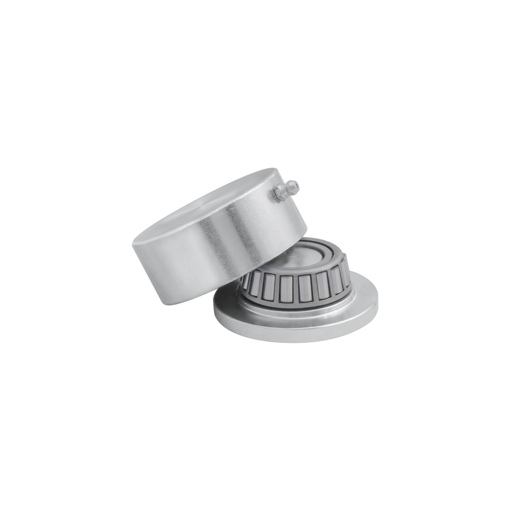
455.4
Lower bearing hinge, intended for weld-on mounting on a swing gate. Product reference 455.4 is listed in the 455 range table. Leaf sizing and welds must be checked separately; a static load does not describe the complete installation.
Manufacturer documentation ↗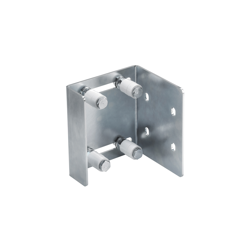
204.1
Bolt-on guide plate with a long adjustment slot and four rollers. Product reference 204.1 corresponds to 30 mm rollers. It enables mechanical upper guidance to be selected according to gate thickness and bracket locations.
Manufacturer documentation ↗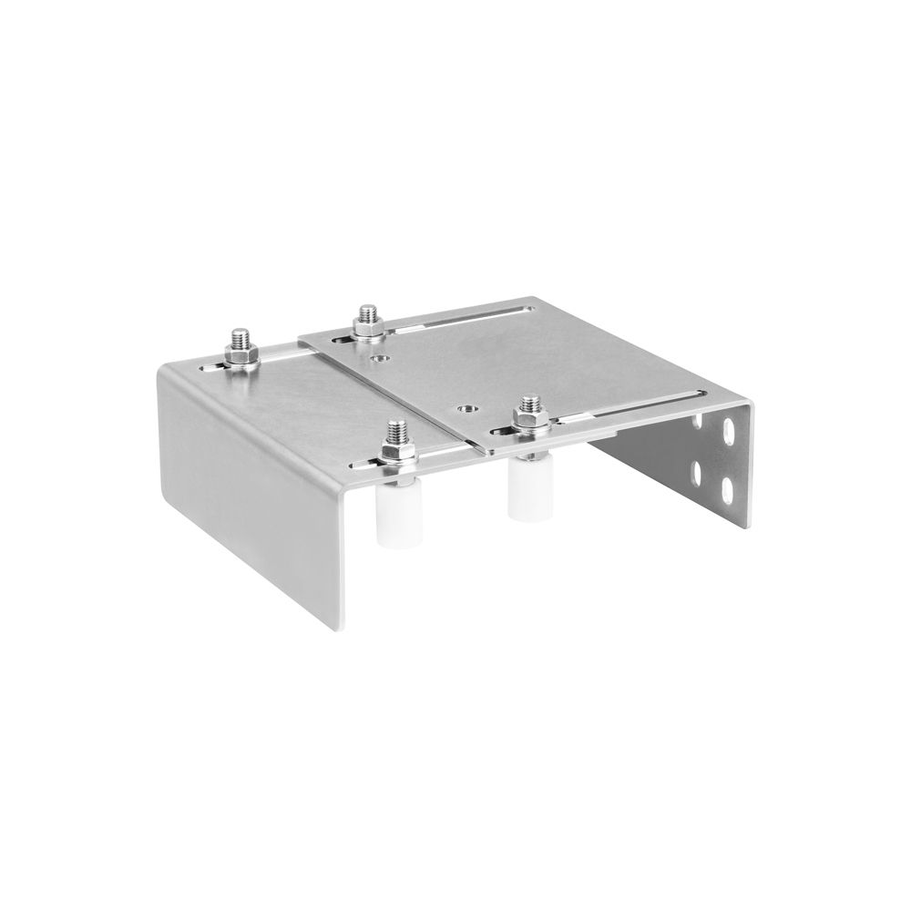
208.32
Adjustable mounting guide plate with four 31 mm rollers according to the Hi-Motions table. Reference 208.32 differs from the two-roller model 208.31. Check the device's space requirements and gate section before choosing this configuration.
Manufacturer documentation ↗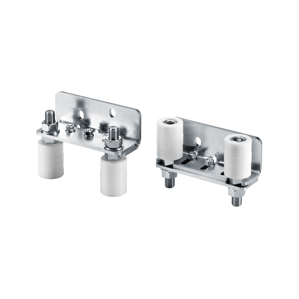
211.2B
Adjustable angle guide with two rollers for mechanical guidance of sliding gates. Product reference 211.2B has 31 mm rollers. Its angled shape must be assessed against the post geometry and available mounting space.
Manufacturer documentation ↗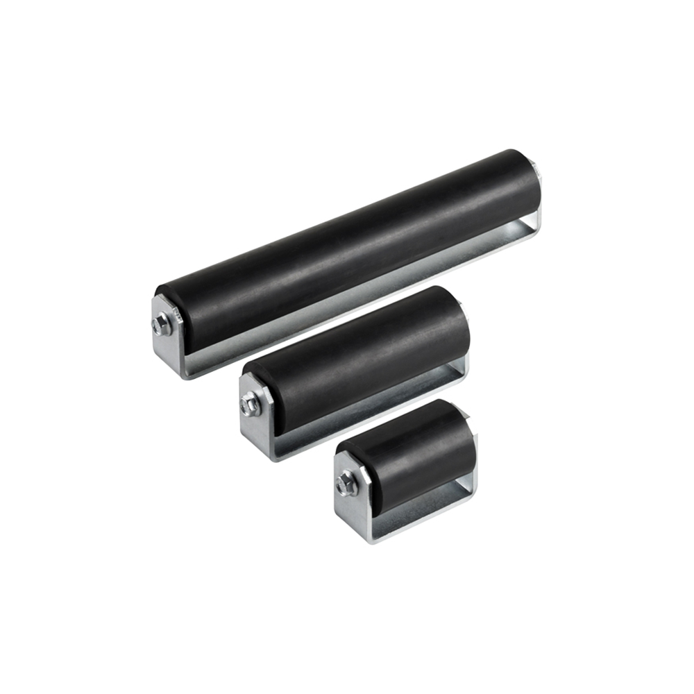
225.06
NBR SH80 rubber guide roller for sliding gates. Reference 225.06 corresponds to the 162 mm length published by Hi-Motions. The range image shows several lengths; the selection covers this code only, not a set of three rollers.
Manufacturer documentation ↗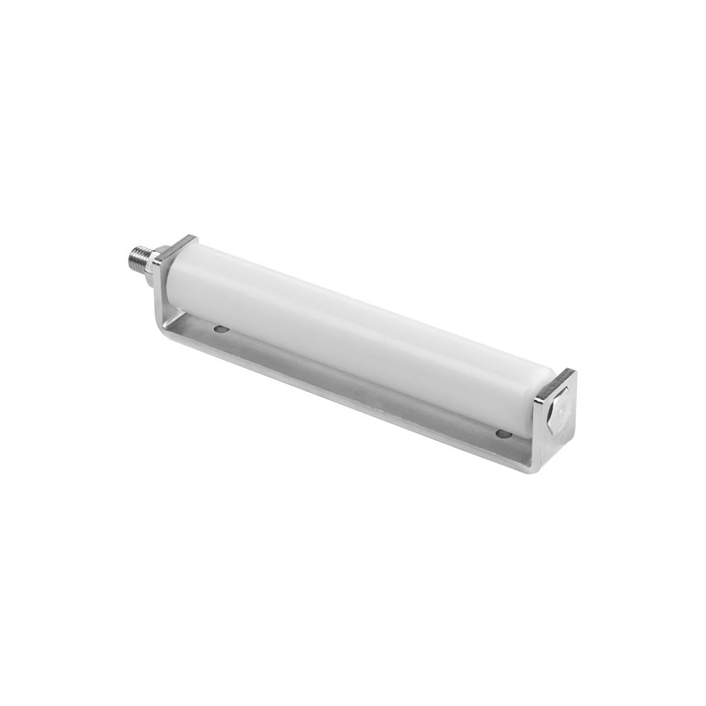
231.0
White nylon guide roller on a mounting plate, identified by code 231.0. Hi-Motions states a length of 247 mm on its product page. Select this component according to the required contact length and the ability to attach its plate.
Manufacturer documentation ↗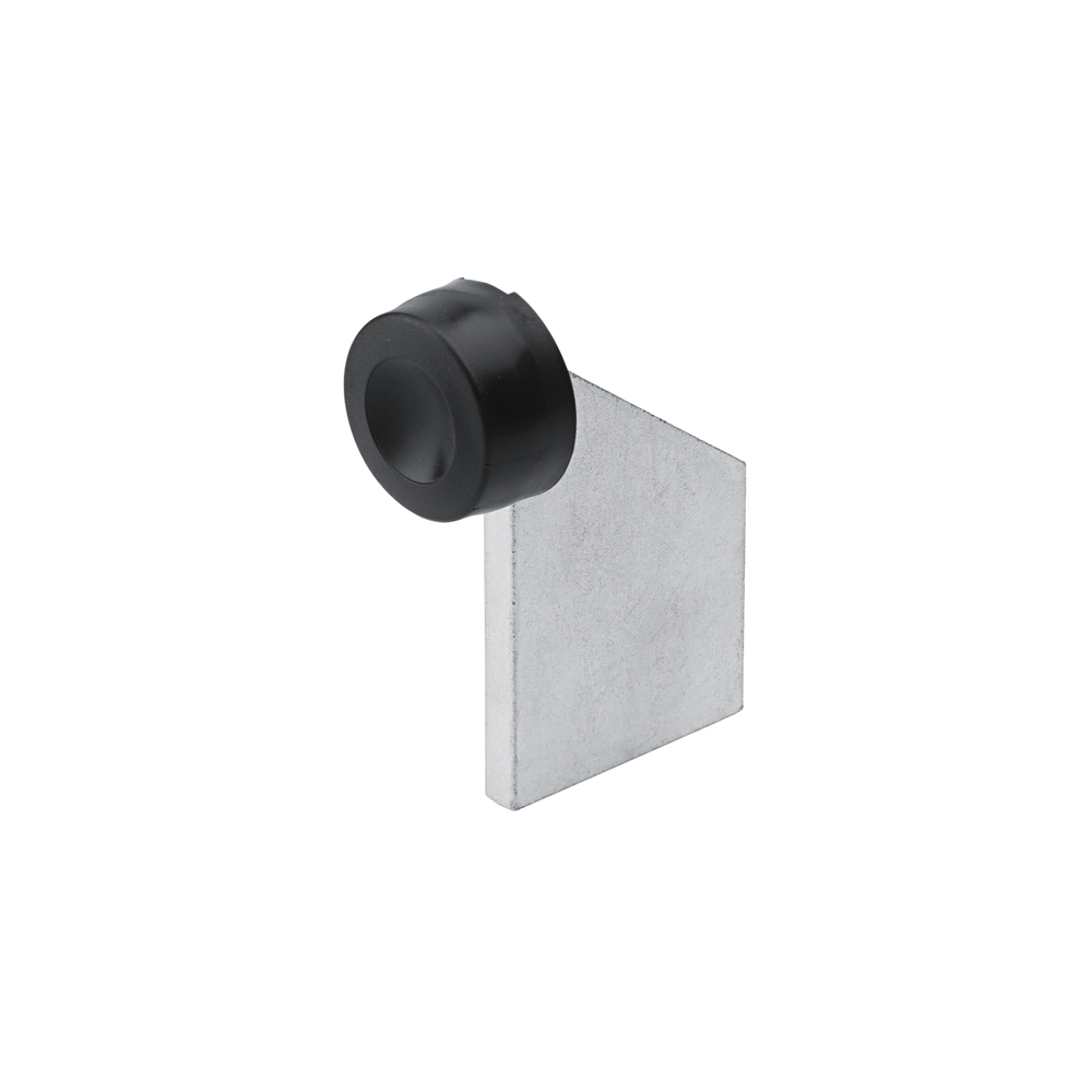
241.1
Weld-on mechanical stop presented among Hi-Motions hinged gate accessories. Reference 241.1 identifies the model to request within range 241. Define the stop position and welding support according to the gate travel.
Manufacturer documentation ↗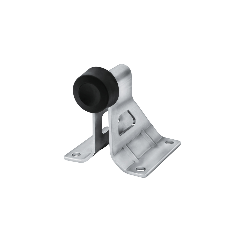
243.2
Mechanical gate stop supplied with a profiled mounting plate, listed by Hi-Motions as 243.2. The official image shows the buffer and its bracket. The plate shape allows mounting to be planned with regard to the support and desired stopping point.
Manufacturer documentation ↗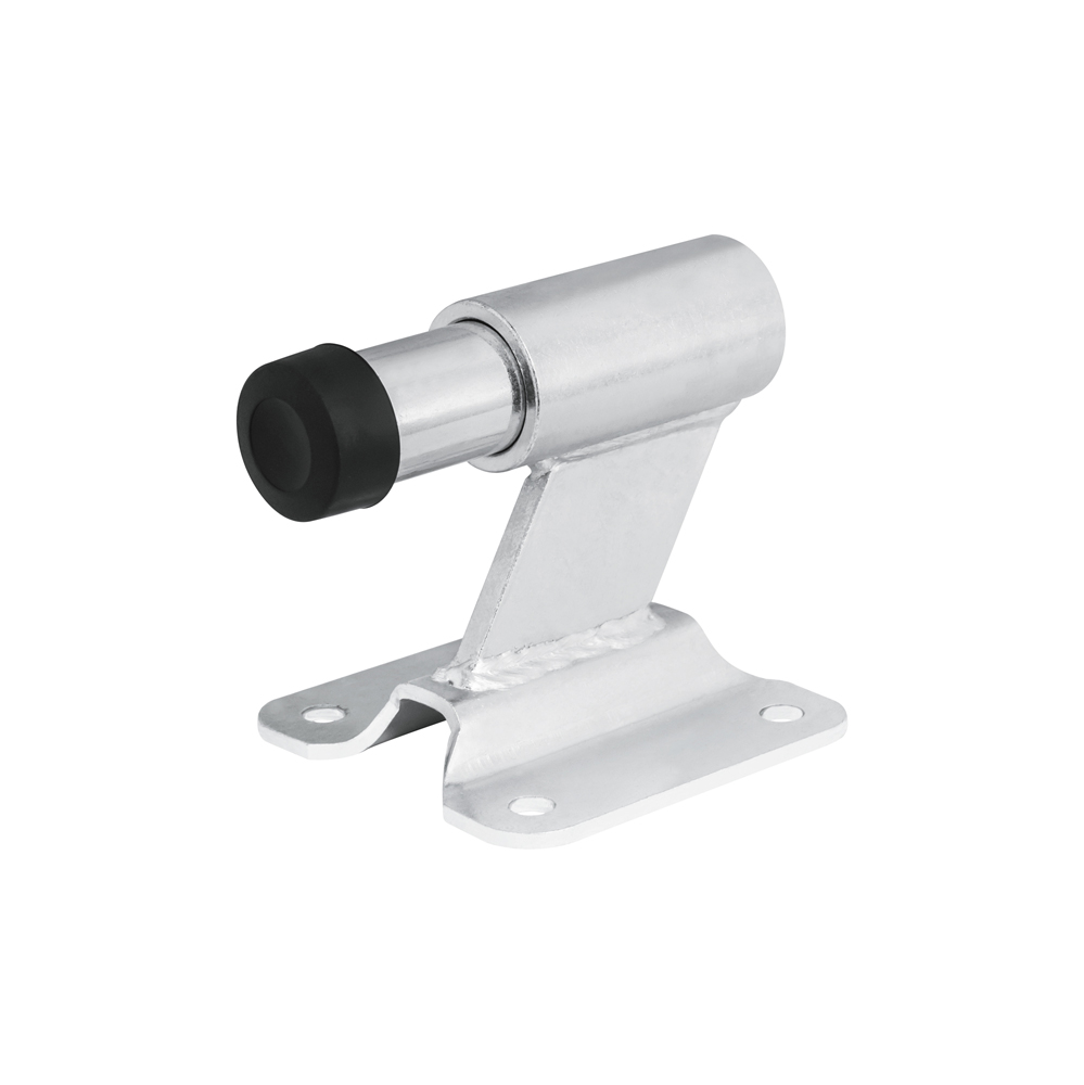
245.3
Mechanical spring buffer stop mounted on a fixing plate. Hi-Motions identifies it under code 245.3 in its gate stop range. Select it for the intended mechanical contact point; no electrical detection or safety function is stated.
Manufacturer documentation ↗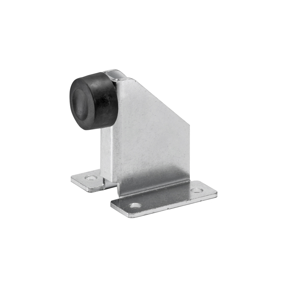
247.1
Bolt-on mechanical stop for swing gates, presented in the 247 range. Selected reference 247.1 appears in the official Hi-Motions table. Its buffer and plate are visible in the range illustration; choose the stopping position and fixings to suit the available support.
Manufacturer documentation ↗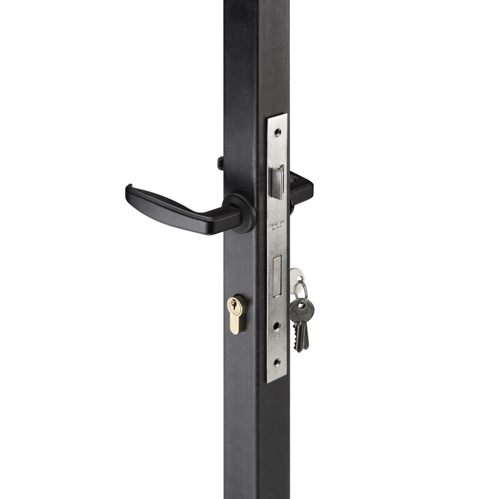
264.0
Lock kit from the 264 range for square sliding gate posts. Reference 264.0 appears in the official Hi-Motions table. The manufacturer image shows installation on a post; detailed kit contents to be confirmed in the quotation.
Manufacturer documentation ↗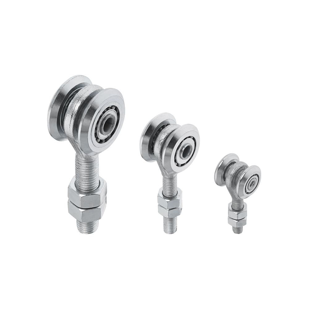
601.42
Two-wheel sliding trolley for Hi-Motions industrial door rails. Code 601.42 corresponds to the 42 mm diameter in the manufacturer's table. The official image shows several range sizes; this sheet selects a single reference.
Manufacturer documentation ↗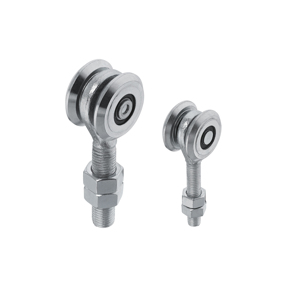
603.42
Industrial door rail trolley with two bearing-mounted wheels. Reference 603.42 has a 42 mm diameter according to Hi-Motions. Determine the compatible rail and load distribution for the complete door before choosing its trolleys.
Manufacturer documentation ↗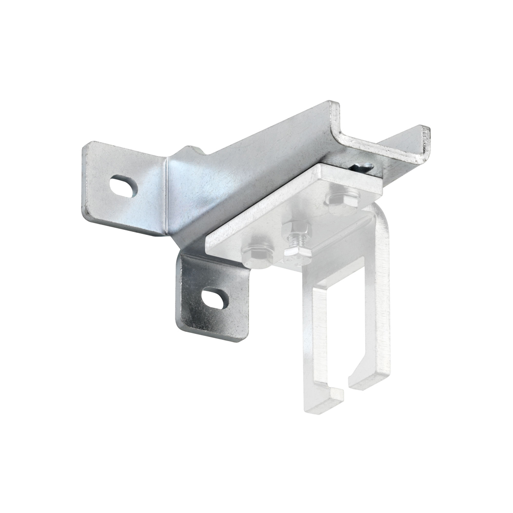
630.11
Wall-mount rail bracket for industrial doors, product reference 630.11. Hi-Motions states compatibility with 631.24, 631.42, 631.48 and 631.55. The bracket combination and rail must be selected together; the official illustration shows an installation example.
Manufacturer documentation ↗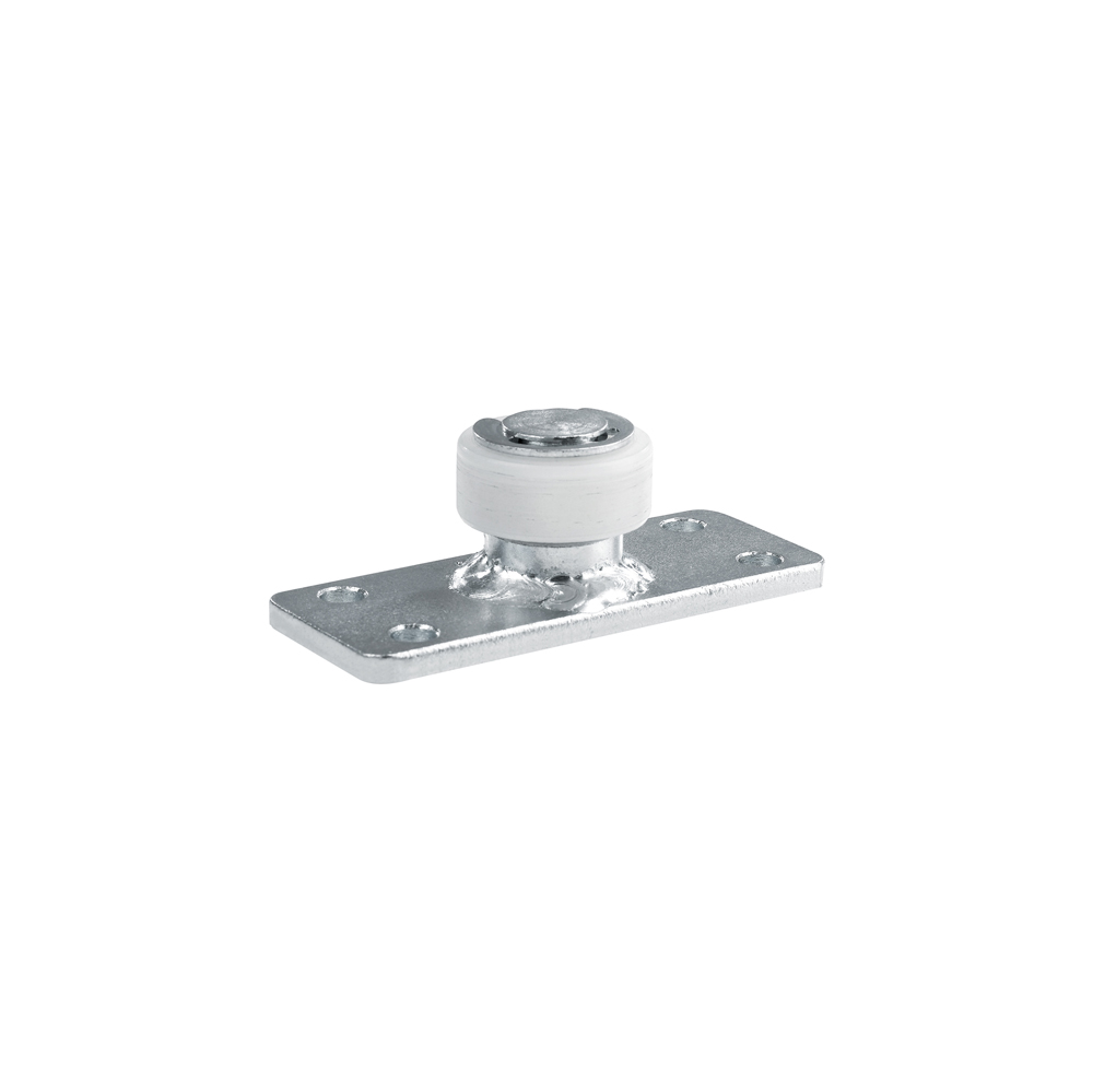
641.42
Upper nylon roller with a four-hole mounting plate for industrial doors. The Hi-Motions table associates product reference 641.42 with a 42 mm diameter. Position this guide according to the door geometry and suspension system.
Manufacturer documentation ↗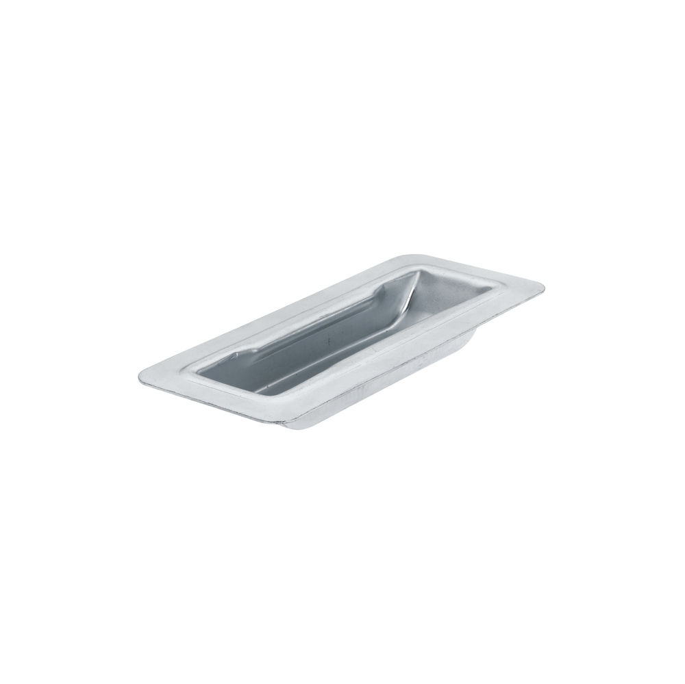
650.0
Recessed cup handle for industrial doors, identified by Hi-Motions as code 650.0. The table specifies that this version has no mounting holes. It differs from the drilled 650.F variant; integration into the door must be planned accordingly.
Manufacturer documentation ↗